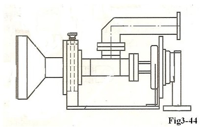
The feed system of Flyaway Antenna is composed of feed source and duplexer, mounted on the feed pedestal. The feed pedestal is fixed on the bottom of main reflector’s locating face, complementary with rod to ensure the correct position of feed source.
Maybe you don’t know flyaway antenna, if you’d like to know much more information about flyaway antenna, please visit the website Flyaway Antenna Introduction
As shown in Fig3-44, loosen the locking device of feed source, and rotate duplexer. In the way it can adjust the polarization.
The feed strut is ¢45mm×2mm aluminum alloy tube with BJ-120 aluminum waveguide passing through the middle. To ensure correct connecting of waveguide, all waveguide ends of joint are non-standard joint, as shown in Fig 3-45. 
The length of struts is 531mm and root connector is 59mm to ensure compactness of package.(the part is fixed on the flyaway antenna and not dismounted).
The whole support structure (including horn, duplexer, rotary joint, strut waveguide, etc.) weighs 1.8kg, which is the important part of the whole flyaway antenna structure, if you’d like to get much more information about the whole flyaway antenna structure, please visit the website An Introduction for Flyaway Antenna Structure
It is simple and reliable to connect feed strut and root. Insert one end and point the other to locating pin, hitch to straight knurl nut of strut and then lock. There is waveguide flange on the other end of connector. Connect bend waveguide to power amplifier of the backside flyaway antenna (This section is fixed and not removed).
The complete feed system has 2 flange (one with±90 scale) supporting on panel of feed strut. When adjusting, loosen flange screw with scale, rotate duplexer in place, and then lock the screw.
More over, for the flyaway antenna maintenance, please visit at Flyaway antenna maintenance

