Flyaway Antenna Web
Flyaway Antenna Web
Flyaway antenna Introduction,Portable antenna Report ,Installation,Maintenance
  • HOME
  • Blog
  • Contact Us
Menu back  
Flyaway Antenna

Flyaway antenna is of offset antenna, which is comprised of reflector, feed system,  azimuth adjusting mechanism, elevation adjusting mechanism and tripod pedestal. The  antenna is packed in a backpack or a box, which can also be loaded in automobile cars.

According to the antenna latitude/longitude and assigned Satellite parameters,  Flyaaway antenna can capture the Satellite quickly by manual; Flyaway antenna has no  restriciton of traffic conditions and regional environment, which can realize reliable  high-qualified audio and data communication.

Flyaway antenna adopts carbon fiber or aluminum material and has the features of light  weight and high strength; also with good performance of cross polarization  discrimination, low sidelobe and high efficiency; It is convenient to do the assembly  and disassembly and simple to do the adjustment, no need to do the installation by any  device, one person can finish the assembly within 3 minutes. One whole reflector is  consisted of several panels, which can reduce the collection volume and easy to do the  transportation.

Manufacturers Recommend

®Antesky Science Technology Inc

E-mail:sales@antesky.com

Tel:0086-29-88352448

Skype:carolyn.zyy

Attention Points for Using Flyaway Antenna

As for the flyaway antenna station, the antenna is the main equipment which is also easily damaged at the same time. When disassembling the antenna panels, please take them lightly, and don’t knock against the antenna surface. And don’t contact corrosive strong acid and alkali to avoid damaging antenna surface. More information about flyaway antenna, please visit Flyaway Antenna Introduction

The Flyaway antenna strut plays a role of supporting feed as well as routing waveguide. Thus feed strut must be kept dry and clean, and don’s knock.  Please assemble carefully when assembling feed strut. More information about the flyaway antenna structures, please visit An Introduction for Flyaway Antenna Structure

Feed system is the center of the antenna. The film material of feed surface is polytetrafluoroethylene which has a role of dustproof and rainproof. And please pay attention to protect and prevent feed membrane from damage. If you’like to get more information about the flyaway antenna feed system, please visit Introduction for Flyaway Antenna Feed system

Without the permission of Antesky Inc. Any individual or group is not allowed to cite or release this article.

Flyaway Antenna Introduction

Flyaway antenna is satellite communication antenna with the advantage of miniaturization and portability. It possesses many characteristics, including small volume, light weight, quick and convenient to install, and high precision of reinstalling. In general, the flyaway antenna is placed in a knapsack of a small box.

Portable antenna can be divided into two categories: prime focus and offset antenna on the basis of feed source position. It can be fall into two categories: aluminum and fiber antenna in the light of material. According to diameter, Portable antenna can be divided into 0.75m, 0.98m, 1.2m and 1.8m flyaway antenna.

Portable antenna can support such communication service as voice, data and fax.

Flyaway antenna is available for a wide range of applications containing remote areas, island, village, oil filed, mina area, finance, transportation, civil aviation, environment, waterpower, electric power, geology, salvage, rescue, and emergency. Flyaway antenna can solve the problem that wired communication, such as electric cable and optical fiber, don’t serve and don’t open at any time. Portable antenna can also solve the problem of instability of wired communication and limitation of communication service. If you’like to get some more information when you use flyaway antenna, please visit the website: Attention Points for Using Flyaway Antenna

Additionally, for the flyaway antenna maintenance, please visit at Flyaway antenna maintenance

An Introduction for Flyaway Antenna Structure

In order to embody portable performance, make sure the flyaway antenna characteristics of light weight, small geometry size in package, quick and convenient assembly, high precision of reassembly in the design. For flyaway antenna introduction, please visit the website: Flyaway Antenna Introduction.

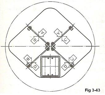
In order to reduce flyaway antenna weight, carbon fiber composite material is adopted in the reflector. The reason is the carbon fiber composite materials possess characteristics of light weight, high modulus, and a low coefficient of thermal expansion. There are various structures to make flyaway antenna reflector with carbon fiber. And honeycomb sandwich construction is widely adopted because of high rigidity, light weight and convenient to do the production. Flyaway antenna adopts honeycomb sandwich construction with aluminum. Carbon fiber itself possesses conductivity, but not as well as metal. Carbon fiber becomes poor conductor because resin exists basically. So the flyaway antenna reflector needs metallization. Method of metal ion transference is introduced to metalize the portable antenna. The shape of flyaway antenna reflector is optimized in design, and the geometric dimension is reduced so as to pack conveniently. The eternal outline of the flyaway antenna reflector is quadrilateral, which consists of four 350*350 small quadrilateral reflector. The illustrated diagram of flyaway antenna panel is shown in Fig 3-43.

flyaway-antenna

There are location and fast connection device between all block panels to make sure of quick assembly and high precision reassembly. And there needs no tool when assembling. The weight of flyaway antenna reflector is less than or equal to 7kg.

Additionally, for the flyaway antenna maintenance, please visit at Flyaway antenna maintenance

Introduction for Flyaway Antenna Feed system

The feed system of Flyaway Antenna is composed of feed source and duplexer, mounted on the feed pedestal. The feed pedestal is fixed on the bottom of main reflector’s locating face, complementary with rod to ensure the correct position of feed source.

Maybe you don’t know flyaway antenna, if you’d like to know much more information about flyaway antenna, please visit the website Flyaway Antenna Introduction

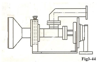
As shown in Fig3-44, loosen the locking device of feed source, and rotate duplexer. In the way it can adjust the polarization.

flyaway-antenna

The feed strut is ¢45mm×2mm aluminum alloy tube with BJ-120 aluminum waveguide passing through the middle. To ensure correct connecting of waveguide, all waveguide ends of joint are non-standard joint, as shown in Fig 3-45.

The length of struts is 531mm and root connector is 59mm to ensure compactness of package.(the part is fixed on the flyaway antenna and not dismounted).
The whole support structure (including horn, duplexer, rotary joint, strut waveguide, etc.) weighs 1.8kg, which is the important part of the whole flyaway antenna structure, if you’d like to get much more information about the whole flyaway antenna structure, please visit the website An Introduction for Flyaway Antenna Structure

It is simple and reliable to connect feed strut and root. Insert one end and point the other to locating pin, hitch to straight knurl nut of strut and then lock. There is waveguide flange on the other end of connector. Connect bend waveguide to power amplifier of the backside flyaway antenna (This section is fixed and not removed).

The complete feed system has 2 flange (one with±90 scale) supporting on panel of feed strut. When adjusting, loosen flange screw with scale, rotate duplexer in place, and then lock the screw.

More over, for the flyaway antenna maintenance, please visit at Flyaway antenna maintenance

Flyaway antenna pedestal structure

The flyaway antenna pedestal consists of azimuth adjusting device, elevation adjusting device and strut leg. The weight is 6.5kg. Before you know the flyaway antenna pedestal structure, maybe you’d like to know much more information about flyaway antenna, please visit Flyaway Antenna Introduction.

Each part of flyaway antenna pedestal can be demounted manually, loaded in bags, and removed and repaired by one person. When assembling flyaway antenna, take parts out from box and assemble manually. Three groups of pedestal support can choose reinforcement and wind-resistance measurement. Nail individually on three foot drives. Or press a sandbag on each strut to fasten fixed pedestal and adjust torsion bar to keep pedestal in horizontal level. For more information about the whole flyaway antenna structure, please visit An Introduction for Flyaway Antenna Structure.

· Azimuth adjusting mechanism
Azimuth adjusting device mainly consists of azimuth turntable, star screw. When roughly adjusting, adjust triangle support. When fine adjusting, loosen star screw and drive azimuth turntable and then can adjust antenna’s azimuth angle (-30~30°). Lock star screw in the time of locking.

·Elevation adjusting mechanism
The mechanism is lead screw adjusting. One end is fastened on pedestal; the other end is connected with flyaway antenna reflector. When adjusting El, press knurl tightly and lock jacking block of screw to adjust in a wide range. And then loose jacking block, rotate knurl nut to adjust fine. The elevation range is between 15~50°when using lead screw. The El adjusting mechanism is shown in Fig3-46.

flyaway-antenna

Additionally, for the flyaway antenna maintenance, please visit at Flyaway antenna maintenance.

Flyaway Antenna Maintenance

Flyaway antenna plays a very important part in satellite communication. More information about flyaway antenna, please visit Flyaway Antenna Introduction. The antenna works outdoors. Because of the bad eternal environment, the natural environment in using area is fully taken into consideration at the beginning of design. During use, there is need for regular maintenance and maintenance test to improve service life and communication reliability of antenna.

Check portable antenna structure system totally at regular intervals to ensure that the equipment operates safely and reliably. The equipment is checked under shut-down state.

(1)Watch if equipment appearance, including antenna reflector, feed, LNB, duplexer, etc., is complete, and if the connector is compact. More information about the flyaway antenna feed system, please visit Introduction for Flyaway Antenna Feed system

(2)Watch if there is any breakage on sealing membrane of corrugated horn’s opening. If damaged, it should be renewed in time to prevent feed from inflowing.

(3)Oil feed strut and the connecting hole of feed system at regular intervals

(4)have loop back test at regular intervals to test the unit performance of the feed

(5)Please hit the nail when using the antenna in windy weather, or put pressure on azimuth disc with heavy object. And special person must aware Flyaway antenna constantly to prevent the antenna from blowing out.

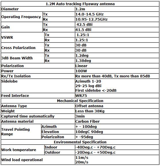
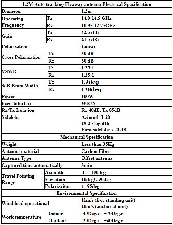
1.2M Auto Tracking Flyaway Antenna

1. Antenna is dual offset, the antenna main support system are using carbon fiber achieved 90%. Antenna is lighter; strength is highter, it’s better for portable use.

2. Gregorian antenna,it make sure antenna with high gain, low sidelobe,and it can meet or exceed most satellite compay requirements.

3. One button to satellite acquisition, auto-deploy and auto-stow in less 3 minutes.

Applications:

1.Sudden public events and all kinds of disasters on-site information gathering

2.Disaster relief

3.Military,government,oil,water conservancy,electricity,finance and other import sectors of the country

4. The remote areas and the vast rural areas out of coverage

5.Field operations, exploration,military police and news media

1.2m Auto tracking Flyaway antenna recommend

flyaway antenna,1.2m flyaway antenna,1.2m Auto tracking Flyaway antenna

Portable auto pointing flyaway satellite communication antenna system includes ACU control unit, auto pointing control unit, switch input unit, motor drive unit and motor unit. ACU control unit consists of programming module, systematic reset circuit, power module and clock module. Auto pointing control unit consists of manual control unit and beacon control unit. Switch input unit consists of up limit switch, down limit switch, left limit switch, right limit switch and input photoelectric isolation circuit. Motor drive unit consists of azimuth motor drive circuit X, elevation motor drive circuit Y, drive photoelectric isolation circuit and control logic circuit. Motor unit consists of azimuth motor X and elevation motor Y.

The characteristics of 1.2m Auto tracking Flyaway antenna system performance are as follows:

1. The antenna is packed in a case, which is convenient to carry, suitable for long highway transportation and taken by two people.

2. The antenna is shaped and assembled by four pieces of aluminum panels, with characteristics of large rigidity, light weight, high precision of profile, and convenient assembly.

3. The antenna controller possesses function of automatic deploy and reset.  The operation adopts remote control and the equipment is very simple. Automatic satellite search only needs 3 minutes.

4. The antenna controller can prestore parameter of six satellites and automatically align any one of six satellites

5. The antenna controller has azimuth, elevation and polarization angle and display function for satellite signal spectrum.

6. The antenna control with mechanical handle has two categories which are manual and automatic mode.

7. The servo system of satellite antenna adopts three-axis (azimuth, elevation and polarization) automatic control.

8. The antenna is packed in a case, which is convenient to carry, suitable for long highway transportation and taken by two people.

Applications:

1.Sudden public events and all kinds of disasters on-site information gathering

2.Disaster relief

3.Military,government,oil,water conservancy,electricity,finance and other import sectors of the country

4. The remote areas and the vast rural areas out of coverage

5.Field operations, exploration,military police and news media

Operating Principle Of Flyaway Antenna

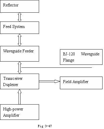
The type of antenna consists of reflector, pedestal and feed system. And its operating principle is shown in Figure 3-47.

Microwave signal sent by high-power amplifier is transferred onto feed system through waveguide feed, and then it is reflected onto reflector from feed radiation. The reflector is rotary paraboloid and the feed is placed in the focal point of rotary paraboloid. After antenna reflector’s reflection, electromagnetic wave radiates towards free space and forms beam. Spatial electromagnetic signal from space is reflected by antenna reflector and converged on the feed, and then transmitted to duplexer through waveguide feeder. The signal which antenna receives is amplified and sent to the receiver by the connection of amplifier and duplexer end. Waveguide feeder connects duplexer with flange plate.

What is Flyaway Antenna

Flyaway antenna is a type of satellite communication antenna with the advantage of miniaturization and portability. It possesses the characteristics of small volume, light weight, quick assembly, and high precision of reassembly. Generally the flyaway antenna is packed in a backpack or a small box.

On the basis of feed position, flyaway antenna can be divided into two categories, which are prime focus and offset antenna. In the market mostly it is offset antenna, which is consisted by reflector, feed system, azimuth adjustable equipment, and elevation adjustable equipment and tripod pedestal mount. On the basis of the material, it can be divided into two categories, which are aluminum and fiber antenna.

Such communication service as voice, data and fax can be supported by flyaway antenna.

Flyaway antenna is available for a wide range of applications,including remote district, island, village, oil filed, mining area, finance, transportation, civil aviation, environment, waterpower, electric power, geology, rescue, relief and emergency. It can solve the problem that wired communication, such as electric cable and optical fiber, can’t cover and open anytime anywhere. It can also solve the problem of instability of wired communication and singularity of communication service.

Flyaway antenna Report
Flyaway Antenna
December 10, 2015
1.8m C band flyaway antenna for sale
December 9, 2015
1.2m vsat flyaway antenna for sale
December 9, 2015
2.4 meter fly-away antenna for sale
December 9, 2015
1m flyaway dish for sale
December 9, 2015
antena fly away
December 9, 2015
flyaway vsat antennas
December 9, 2015
1.8m flyaway antenna for sale
November 27, 2015
1.8m flyaway vsat antenna for sale
November 20, 2015
1.8m antenna flyaway for sale
November 20, 2015
Recent Posts
  • Flyaway Antenna
  • 1.8m C band flyaway antenna for sale
  • 1.2m vsat flyaway antenna for sale
  • 2.4 meter fly-away antenna for sale
  • 1m flyaway dish for sale
  • antena fly away
  • flyaway vsat antennas
  • 1.8m flyaway antenna for sale
  • 1.8m flyaway vsat antenna for sale
  • 1.8m antenna flyaway for sale
  • 1.2m Auto tracking Flyaway antenna recommend
  • 1.0M Auto Pointing Flyaway Antenna System
  • 1.2M Flyaway Antenna Application
  • Operating Principle Of Flyaway Antenna
  • What is Flyaway Antenna
  • Application and Development of Flyaway Satellite Station in News Gathering System
  • The Structure and Composition of Flyaway Antenna
  • Flyaway Antenna Maintenance
  • Flyaway antenna pedestal structure
  • Introduction for Flyaway Antenna Feed system
Manufacturers
Antesky Science Technology Inc
Andrew Corporation
SATCOM Technologies

VSAT Antenna | Tvro Antenna | 0.55M Flyaway Antenna | 0.75M Flyaway Antenna | 0.9M Flyaway Antenna | 1M Flyaway Antenna | 1.2M Flyaway Antenna | 1.8M Flyaway Antenna
Copyright information @ Flyaway Antenna Web